
Remington 700 Action Blueprinting and Rebuild
Typical Model 700 rebuild steps in Adobe(r) PDF.
Manufacturability of the Remington Action is such that the action is produced within specified tolerances which is a trade-off between cost and accuracy. The purpose of blueprinting the action is an attempt to make the tolerances a close to perfect as possible. The Remington 700 Action is produced from steel tubing and therefore has a centerline reference. In order for the action to be as accurate as possible this centerline must be held as close to true as possible which means machining the face of the receiver, the recoil or locking lugs, and the barrel threads in relation to that centerline. The bolt, firing pin, and the barrel must also align to the centerline of the action to ensure maximum accuracy.
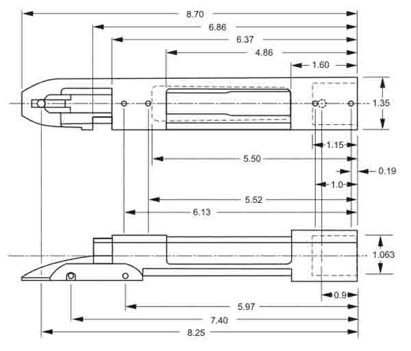
Figure 1 below illustrates some of the basic dimensions of the Remington 700 Action for reference.
The steps involved in blueprinting the action are based on what machining steps can and should be taken to improve the accuracy of a standard manufactured action and bolt. The steps are as follows:
1. True the action in reference to the centerline.
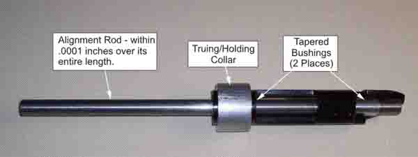
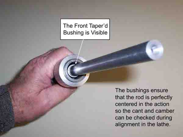
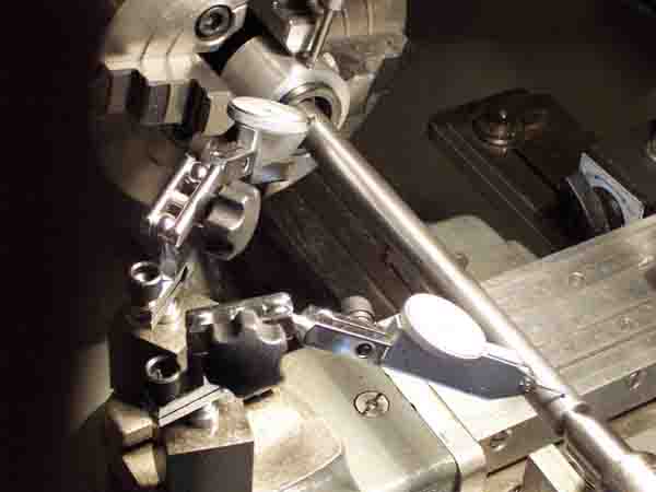
a. Setup the action so the manufactured centerline is establised. This may be done several different ways using jigs that may be purchased or made. An example of one such approach is provided in the figures below.
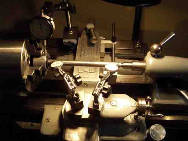
b. Turn the face of the action so it is as close to perpendicular to the centerline as possible. See the figures below for an illustration of how this may be setup.
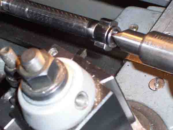
c. Chase the barrel threads to ensure that they are parallel to the centerline of the action. There are several methods of doing this.
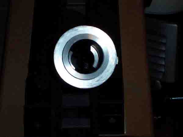
d. Ensure that the shoulders, on which the recoil (locking) lugs engage, are perpendicular
to the centerline and that they engage the locking lugs fully. See the figure below as an example of what trued action face and shoulders should look like.
2. True the bolt in reference to the centerline.
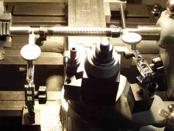
a. Turn the bolt lugs so that they are perpendicular to the centerline and are true in relation to each other. There are multiple methods of performing this and an example of one method is illustrated in the figures below. Once the lugs and recoil shoulders are machined the final step to ensuring a proper match is to lap these two components together for a perfect match.
b. Ensure the firing pin hole is true to the centerline and is .065 +/- .010 inches in diameter. Firing pin diameters must match their associated hole diameter as close as possible without sticking or binding. Hole diameters of greather than .075 inches pose the danger of pierced or cratered primers while hole diameters of less than .055 inches produce unreliable primer ignition.
c. Ensure the bolt face is perpendicular to the centerline.