
CZ52
Download the CZ52 Detailed Strip Instuctions in Adobe(r) PDF.
- Disassembly Instructions
- Firearm Field Strip
- Slide Assembly Detail Strip
- Barrel Assembly Detail Strip
- Magazine Detail Strip
- Receiver Detail Strip
- Assembly Instructions
CZ52 Detail Strip, Disassembly, and Assembly Instructions
©2008 Lonestar Fabrication & Design
These instructions may be freely distributed and copied providing this page is included, and providing they are not used for commercial purposes or monetary gain. These instructions are being provided “as-is” without implied warranty. Users of these instructions shall not hold Lonestar Fabrication & Design accountable for any loss, damage, or injury as the result of these instructions.
CZ52 Detail Strip Disassembly and Assembly
1. Introduction and General Information
The CZ52 (also known as a Vzor 52 or VZ52) is a roller locked short recoil blowback style auto loading pistol designed by the Kratchovil brothers for the Czechoslovakian Army in 1952, hence the name “CZ52.” The CZ52 is designed for the very hot 7.62 x 25mm TT or M4 ammunition.
The parts of the CZ52 are illustrated in Figure 1-1 below. The names and numbers for parts illustrated in this figure will be used throughout these instructions to provide a basic visual identification and reference.
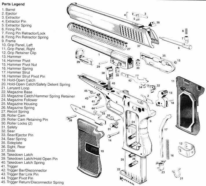
Figure 1-1. CZ52 Schematic
![]() Before doing any work on your firearm always clear the magazine and the chamber!
Before doing any work on your firearm always clear the magazine and the chamber!
![]() The de-cocking safety on the CZ52 is a poor design and may be unsafe so never de-cock with a live round in the chamber unless the gun is pointed in a safe direction of fire!
The de-cocking safety on the CZ52 is a poor design and may be unsafe so never de-cock with a live round in the chamber unless the gun is pointed in a safe direction of fire!
![]() Dry firing the CZ52 with a factory firing pin may result in a broken firing pin!
Dry firing the CZ52 with a factory firing pin may result in a broken firing pin!
a) Remove magazine assembly by pulling down on the forward lip of the magazine base (22) while pulling rearward on the magazine catch / hammer spring retainer (23)
b) Remove slide assembly by pulling down on the takedown latch (38) while lifting and pulling slightly forward on the slide (37)
c) Remove the barrel assembly from the slide assembly by placing a pin punch in the hole of the roller cam (28) and pulling toward the front of the slide while also applying outward pressure to force barrel separation. Note: The barrel will have to move from two to three inches past the barrel bushing in the slide (37) before it can be separated from the slide (37). The CZ52 manual says to use the magazine for this task, however, doing so may bend or kink the magazine base (22)
d) Remove left grip panel (10) and right grip panel (11) by carefully prying underneath either side of the spring loaded grip retainer clip (12) with a common flat blade screwdriver.
Note: Because I haven’t identified the size of the pins in this procedure, you should keep all pins with the assemblies as you remove them from your firearm. I do however make some general notes about them in the assembly instructions.
Note: Detail strip should be fairly intuitive and I have found it easier to strip a firearm than to reassemble it. I am providing some general notes below about the steps however you may wish to refer to the assembly procedures for more information if needed.
2. Slide Assembly Detail Strip
a) Remove the firing pin (6) from the slide assembly by holding the slide (37) barrel end upward and depressing the firing pin retainer / lock (7) with a punch – it will have to go below flush for the firing pin (6) to fall out. You may have to press in and out on it to get the firing pin (6) to fall out. The firing pin (6) should just fall out, if not you may need to soak it in a solvent because it is binding. If you find it really stubborn you may need to press on it at the firing pin hole while depressing the firing pin retainer / lock (7). Refer to Figure 6-1 and 6-2 as needed. Once the firing pin (6) falls out, the firing pin retainer / lock (7) and the firing pin retractor spring (8) are free to be lifted out.
b) Remove the extractor (3) by drifting out the extractor pin (4) as shown in Figure 2-1A and B. Leave the pin punch in place and slowly remove it to control release of the extractor (3), and the extractor spring (5) which are under tension. Note the direction of pin removal because installation will be the reverse of this and the pin punch will be chased out of the slide (37) using the extractor pin (4).
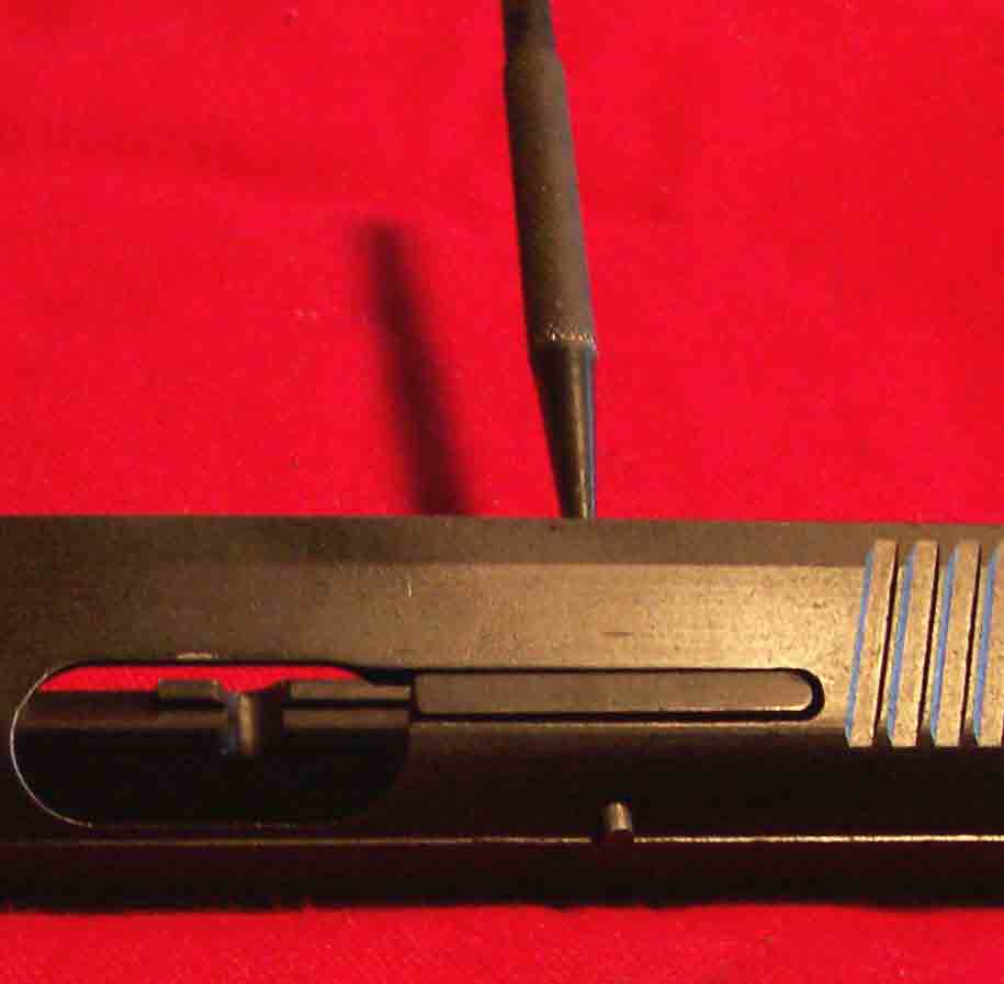
Figure 2-1A. Extractor Pin Removal
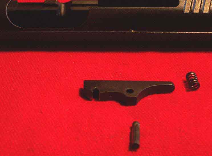
Figure 2-1B. Extractor Assembly Removed
c) The rear sight (36) may be drifted out from either direction using a pin punch. Use care not to scratch the slide (37).
3. Barrel Assembly Detail Strip
Note: Removing the roller cam (28) frees the roller locks (30) which have a tendency to drop out and roll around so use care not to lose these items.
a) Use a pin punch to drift out the roller cam retaining pin (29) and slide the roller cam (28) off the front of the barrel.
b) Remove the roller locks (30).
a) Using a small jeweler’s screwdriver, lift the magazine spring from the slot shown in Figure 1-1 between the interface of the magazine base (22) and the magazine housing (25) and carefully slide the magazine base (22) off which is under spring tension by while pulling forward on the magazine base (22).
b) Remove the magazine spring (26). Note the orientation of this spring. It will have to be reinstalled later in the orientation shown in Figure 4-1.
c) Remove the magazine follower (24) by rotating it out as partially illustrated in Figure 4-1.
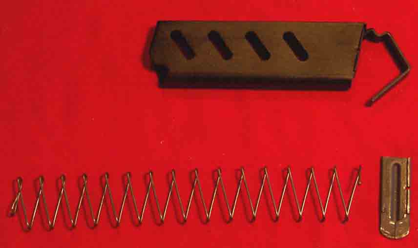
Figure 4-1. Magazine Disassembled.
a) Remove the takedown latch (38) and takedown latch spring (40), which are under spring tension, by drifting out the takedown latch / hold open pin (39) starting from the right hand side of the receiver.
b) Remove the hold open catch (19)
c) Remove the hammer strut (17) and the hammer spring (16) by pressing upward on the magazine catch/hammer spring follower (23) with a common pair of pliers or preferably parallel jaw pliers.
d) Remove the hammer pivot nut (15) from the hammer pivot pin (14) and carefully drift out the hammer pivot pin (14) which will release the hammer (13) so it can be removed. The hammer strut pivot pin (18) may be drifted out if deemed necessary but I usually leave it in the hammer (13).
e) Drift out the trigger pivot pin (44) and the sear/ejector pin (33) and lift out the ejector (2) and remove the sear (32) and sear spring (34) being careful not to lose the sear spring (34).
f) Remove the safety (31) and the hold-open catch/safety detent spring (20) from the left side of the receiver.
g) The sideplate (35) may now be removed by lifting the aft end away from the receiver and sliding it rearward to remove it from the retaining notch at the front. Refer to Figure 7-9 if needed.
h) Remove the trigger (41), trigger bar/disconnector (42), trigger bar link pin (43), and the trigger return disconnector spring (45). The receiver frame (9) should now be stripped of everything except the lanyard loop (21). I normally leave this in but it may be removed by compressing its sides and working it out of the frame (9). I should note that the lanyard loop (21) is much more difficult to install than it is to remove.
The receiver is now detail stripped.
a) Install the firing pin retractor spring (8) and the firing pin retractor lock (7) as illustrated in Figure 6-1. Note the orientation of this assembly because it must be installed correctly in order for the firing pin to properly retract. The firing pin (6) mates with the firing pin retractor spring (8) and the firing pin retractor lock (7) as illustrated in Figure 6-2.
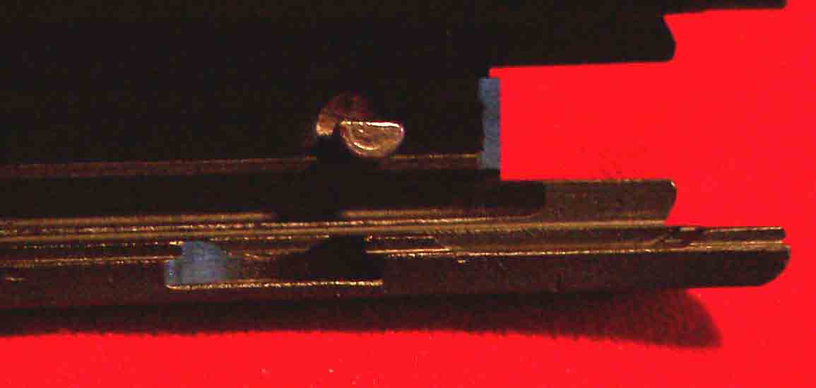
Figure 6-1. Firing Pin Retractor Lock Orientation
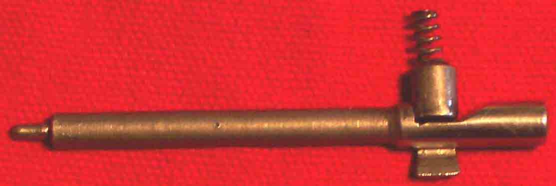
Figure 6-2. Proper Orientation of Firing Pin Parts
b) Install the firing pin (6) as shown in Figure 6-3 and then depress the firing pin retractor lock (7) with your finger or a punch while holding the back end of the slide (37) up – the firing pin should drop into the slide (37). If the firing pin (6) fails to drop easily into the slide (37) then determine the cause, clean as appropriate, or remove any burrs that may exist. Ensure that the firing pin (6) moves and properly retracts by pressing on the rear portion that protrudes at the rear of the slide.
![]() A firing pin that does NOT operate properly or fails to retract may result in a slam fire when the slide is closed on a live round!
A firing pin that does NOT operate properly or fails to retract may result in a slam fire when the slide is closed on a live round!
c) Slide the roller cam (28) most of the way onto the barrel (1) then holding the barrel (1) as shown in Figure 6-3 set the roller locks (30) into place and slide the roller cam (28) completely in place and hold with a pin punch as shown in Figure 6-3. Chase the pin punch out with the roller cam retaining pin (29). The barrel assembly is now complete and the roller cam (28) should move easily back and forth to unlock the roller locks (30) without them falling out.
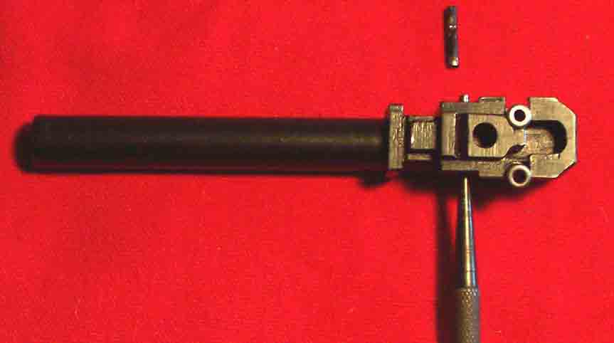
Figure 6-3. Roller Cam Pinned to Hold Roller Locks in Place Until Pin is Installed
d) Install the barrel assembly using a pin punch as illustrated in Figure 6-4A and pulling toward the front of the slide (37) until the barrel seats into slide assembly as illustrated in Figure 6-4B.
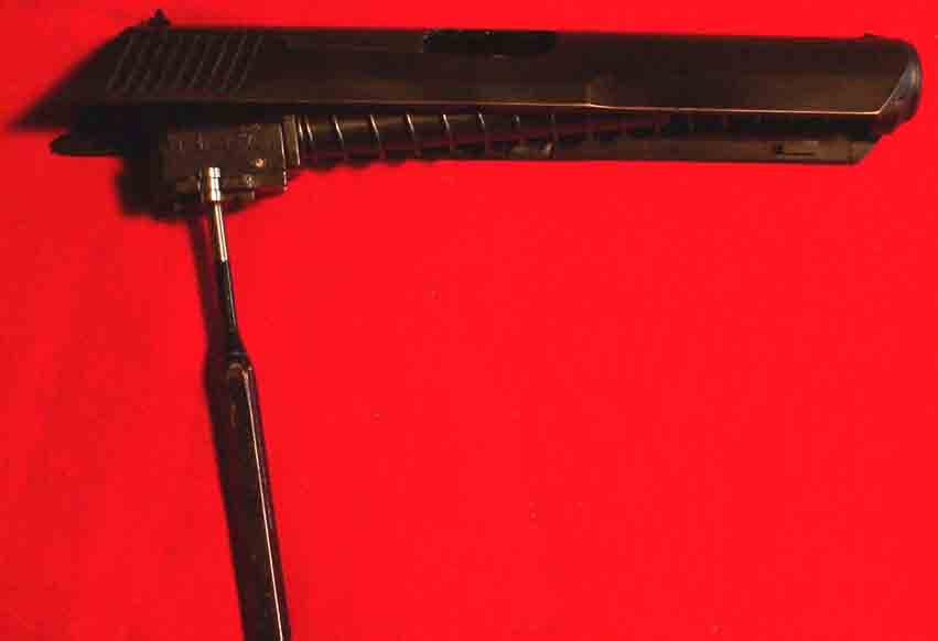
Figure 6-4A. Barrel Installation
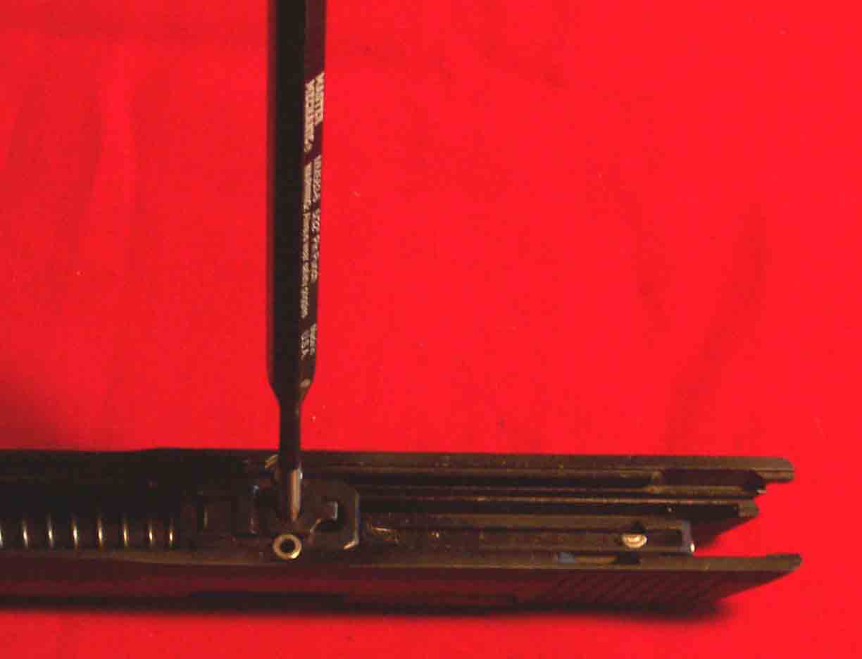
Figure 6-4B. Barrel Installation
a) Trigger Assembly (Figure 7-1) - Install trigger bar/disconnector (42), trigger (41), trigger bar link pin (43) and trigger return/disconnector spring (45) as shown in picture below. Note the position of the trigger spring (45) in the trigger bar/disconnector (42) hole. The spring must also remain on the backside (to the rear of the trigger) after the trigger pivot pin (44) is installed. Note: the trigger bar link pin (43) is shorter than the trigger pivot pin (44). The trigger pivot pin (44) is not shown in Figure 7-1.
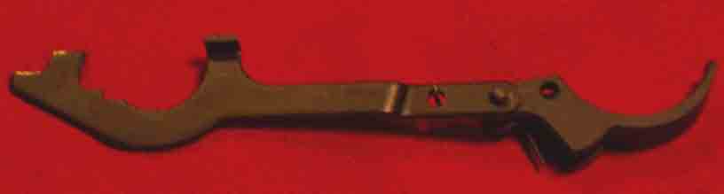
Figure 7-1. Trigger Assembly
b) Install the trigger assembly into the frame (9) as shown in Figure 7-2 using the trigger pivot pin (44). Remember to keep the long tail of the trigger return/disconnector spring (45) to the rear of the trigger pivot pin (44). This should provide adequate tension on the trigger bar/disconnector (42) for it to remain in the position shown in Figure 7-2 while you continue to assembly the receiver.
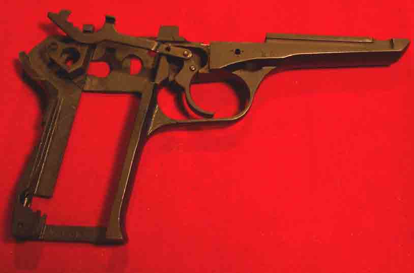
Figure 7-2. Frame with Trigger Assembly
c) Install the hold open catch / safety detent spring (20) in the frame (9) as shown in Figure 7-3.
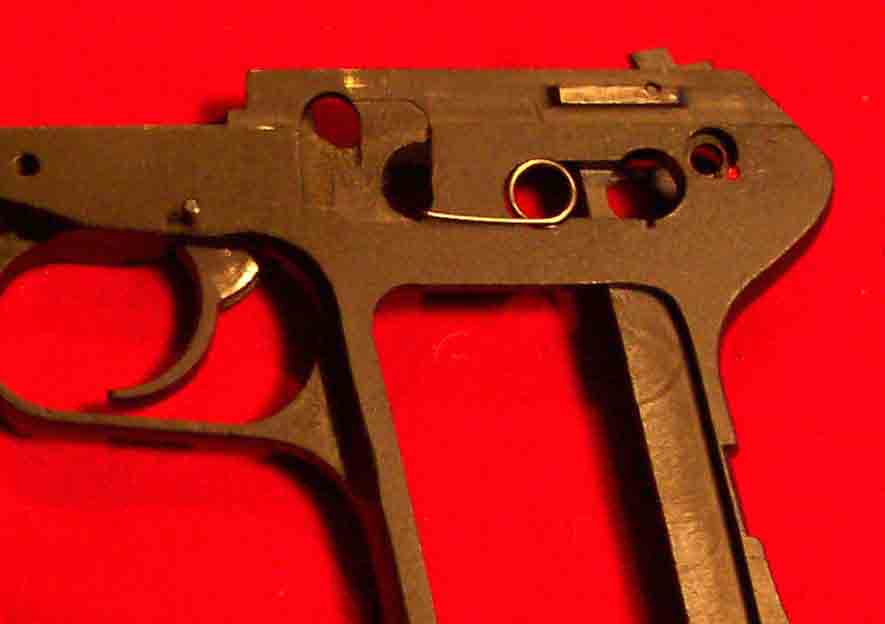
Figure 7-3. Hold Open Catch / Safety Spring
d) Insert the safety (31) and tape it with masking tape as shown in Figure 7-4. The masking tape will help hold the safety (31) in the correct location for step 5 below and prevent it from falling out as you assemble your firearm. It should be noted at this time that the edges and surfaces of the safety (31) should not show strong signs of wear. The CZ52 is notorious for a poor falling safety and many people tell us not to trust it. I will explain how to quickly check it for safe operation once you have the firearm assembled.
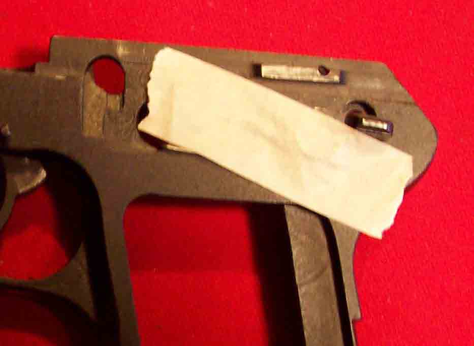
Figure 7-4. Safety Positioning for Sear Installation
e) Insert the sear (32) and sear spring (34) using the sear ejector pin (33) as shown in Figure 7-5A and 7-5B. The ejector (2) is not been installed at this time for clarity in illustrating the steps and may be installed now or later as identified within these instructions. My personal preference is to install it once the sideplate (35) is in place.
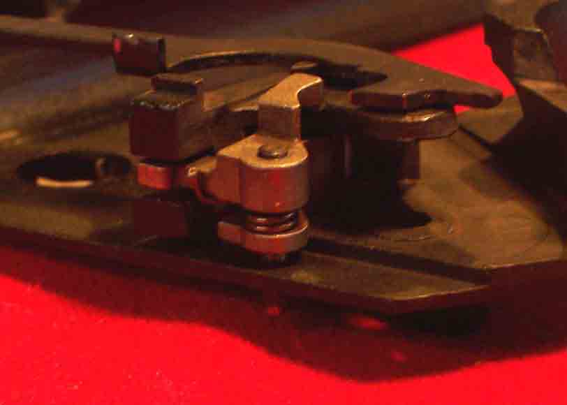
Figure 7-5A. Sear Assembly
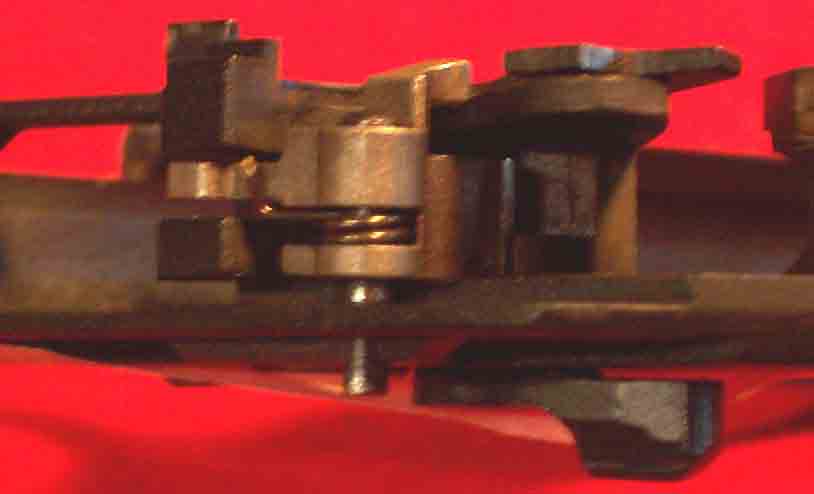
Figure 7-5B. Sear Assembly
f) Once the sear (32) is in place, remove the masking tape and position the safety (31) as shown in Figure 7-6.
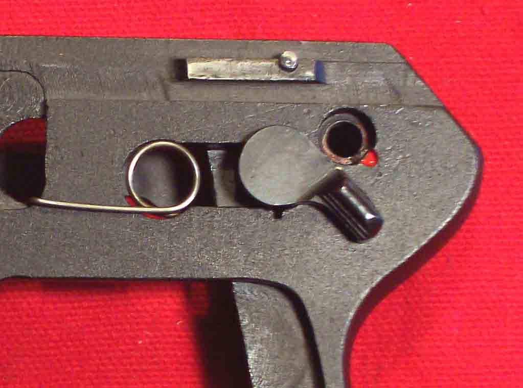
Figure 7-6. Safety Position for Hammer Installation
g) Insert the hammer (13) using hammer pivot (14) as shown in Figure 7-7. Notice the location of the notch in the hammer pivot (14).
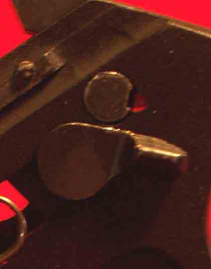
Figure 7-7. Hammer Pivot Pin
h) Position the trigger bar/disconnector (42) as shown in Figure 7-8. This is now the correct location for this item.
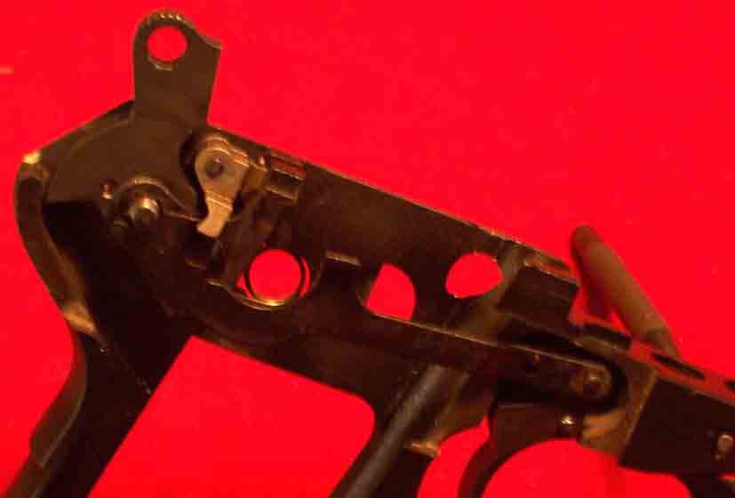
Figure 7-8. Trigger Bar / Disconnector Orientation with Sear
i) Install the sideplate (35) by placing the front lip in the groove as shown in Figure 7-9.
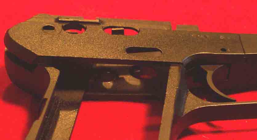
Figure 7-9. Sideplate Installation
j) Press the back of the sideplate (35) down and install the hammer pivot nut (15) on the hammer pivot (14) as shown in Figure 7-10. The hammer pivot (14) may have to be tapped in with a small hammer and brass punch to get it to align properly with the sideplate (35) but be sure the notch is properly set as shown in Figure 7-7 before tapping on it. The trigger pivot pin (44) may now be tapped through the sideplate (35) so it is flush with each side of the receiver.
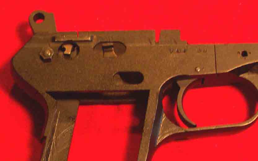
Figure 7-10. Sideplate Installed
k) With a small pin punch, push the sear ejector pin (33) into the sideplate (35) just far enough to drop in the ejector (2) and then press the pin back so it sets below flush on each side of the receiver. This step assumes that the ejector (2) was not previously installed in assembly step 5 above. If it was, then simply make sure that the sear ejector pin (33) sets below flush on each side of the receiver. . . Notice the engagement between the sear (32) and the trigger bar/disconnector (42) clearly visible at the left side of the sideplate (35) hole in Figure 7-11. The hammer (13) should fall back under its own weight when pulling the trigger (41). The trigger bar/disconnector (42) should disconnect from the sear (32) when pressing down on the trigger bar/disconnector (42) tab shown in the center of the oval slot of the right side of Figure 7-11. The trigger bar/disconnector (42) should move freely when pressing down on the tab and then spring back to reconnect when released. The trigger bar/disconnector (42) should not bind or drag when pulling the trigger. If any of these conditions exist, an examination to determine and correct the cause should be done.
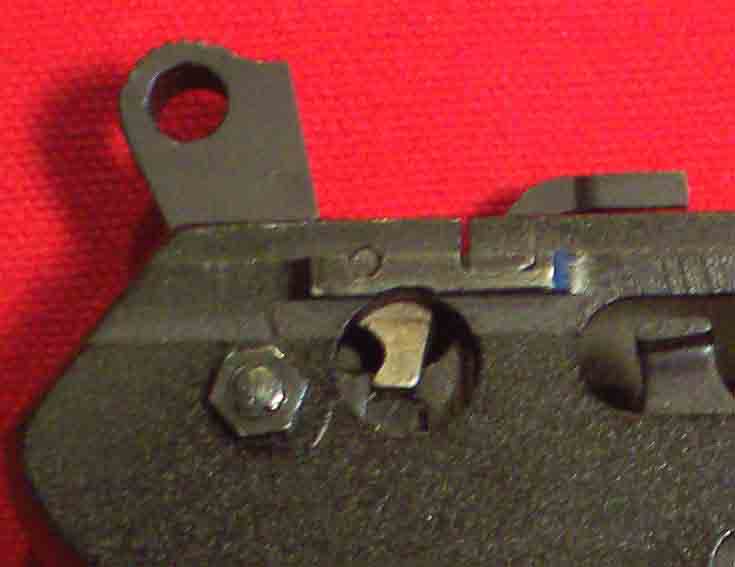
Figure 7-11. Proper Trigger Bar/Disconnector and Sear Engagement.
l) With the hammer (13) in the position shown in Figure 7-11 install the hammer strut (17) and the hammer spring (16) by holding the magazine catch/hammer spring retainer (23) in the jaws either pair of common or parallel jaw pliers. This action is performed more easily by holding the receiver upside down with the hammer (13) resting over the edge of a workbench and pressing down – be sure the ejector is free from pressure and be careful not to get an eyeful of spring or lose it. See Figure 7-12 for the hammer strut spring assembly. Note, if you removed the lanyard loop (21) and wish to have it re-installed, it must be done before installing the hammer spring strut and spring assembly – you may have to tape it back so it won’t fall in the way of the strut installation.
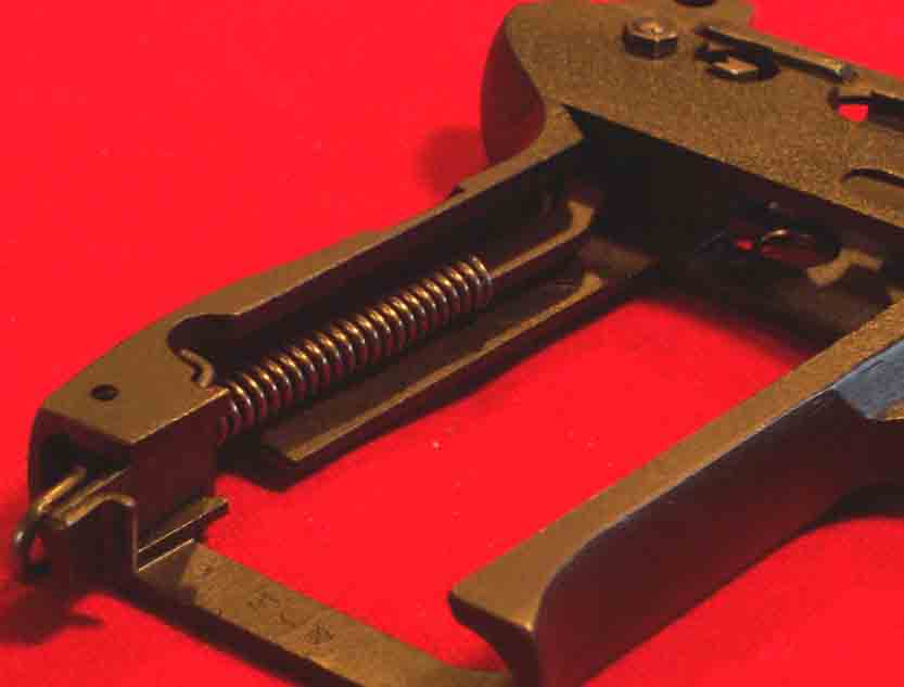
Figure 7-12. Hammer Strut and Spring Assembly.
m) Install hold-open catch (19) using take down latch/hold-open pin (39) as shown in Figure 7-13. Note the hold-open catch/safety detent spring (20) location on the hold-open catch (19). Don’t drive the take down latch/hold-open pin (39) all the way until the take down assembly is held down flush with the top of the frame (9) rails. The take down assembly, consisting of the take down latch (38) and take down latch spring (40) is installed in the orientation shown. You may have noticed that I have installed a hold-open catch (19) that has a thumb slide release. It appears to simply be a piece of shaped metal silver soldered onto the catch – this is not a standard part but I personally prefer it over the standard catch that came with this gun.
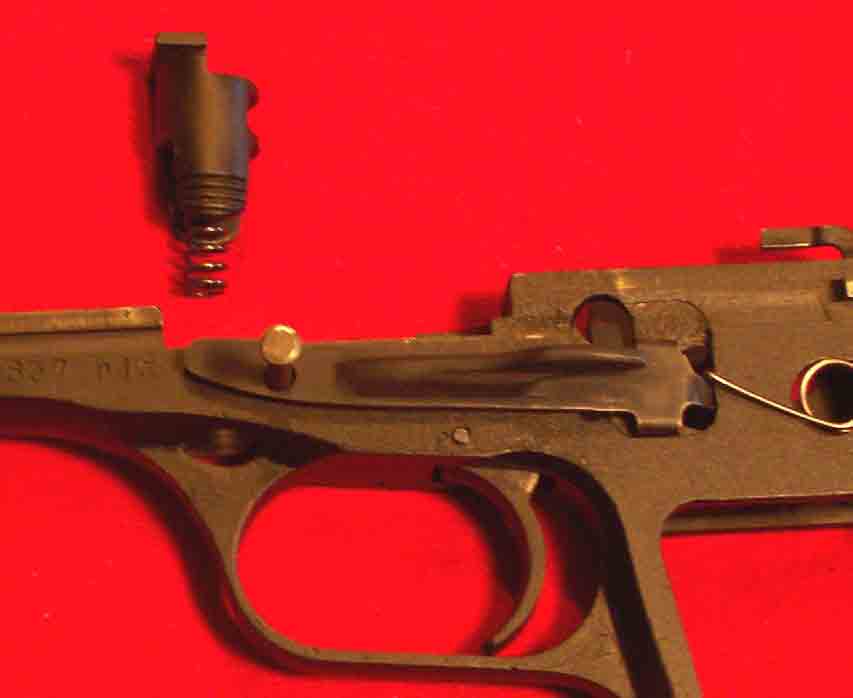
Figure 7-13. Hold-Open Catch and Take Down Latch Installation
n) Install the left and right grip panels (10 and 11) using the grip retainer clip (12) and then install the slide assembly. Your gun should now resemble the one illustrated in Figure 7-14A and B.
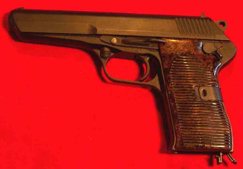
Figure 7-14A. Left Hand Side of Assembled CZ52
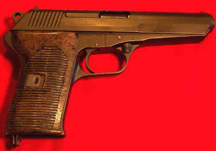
Figure 7-14B. Right Hand Side of Assembled CZ52
o) Test the firing pin operation by placing a ¼” brass rod that is 6 or 7 inches long in the barrel as it is held pointed upward. If the brass rod jumps up when the trigger is pulled then the firing pin is operating properly. Repeat this process but using the safety to decock the hammer – there should be NO jump of the brass rod when the hammer falls from using the safety!